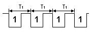
Blocked Mid Times
|
("Time", "GateState1", "GateState2")
"Time": Optional. A column of real numbers (the times of events)
"GateState1": A column of photogate states (1's and 0's)
"GateState2": Optional. A column of photogate states (1's and 0's)
Calculate the average times between blocked events from Gate 1 to Gate
2. If you don't enter a "Time" column, the program will find one. If
you don't enter "GateState2", "GateState1" will be used.
|
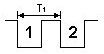
Blocked To Blocked
|
("Time", "GateState1", "GateState2")
"Time": Optional. A column of real numbers (the times of events)
"GateState1": A column of photogate states (1's and 0's)
"GateState2": Optional. A column of photogate states (1's and 0's)
Returns a column of the times between successive blocked events in gate
1 and blocked events in gate 2. If you don't enter a "Time" column, the
program will find one. If you don't enter "GateState2", "GateState1"
will be used.
|
| Blocked To Unblocked |
("Time", "GateState1", "GateState2")
"Time": Optional. A column of real numbers (the times of events)
"GateState1": A column of photogate states (1's and 0's)
"GateState2": Optional. A column of photogate states (1's and 0's)
Returns a column of the times between successive blocked events in gate
1 and unblocked events in gate 2. If you don't enter a "Time" column,
the program will find one. If you don't enter "GateState2",
"GateState1" will be used.
|
| Blocked To Unblocked Midtimes |
("Time", "GateState1", "GateState2")
"Time": Optional. A column of real numbers (the times of events)
"GateState1": A column of photogate states (1's and 0's)
"GateState2": Optional. A column of photogate states (1's and 0's)
Calculate the average time between successive blocked events in gate 1
and unblocked events in gate 2. If you don't enter a "Time" column, the
program will find one. If you don't enter "GateState2", "GateState1"
will be used.
|
| Unblocked to Blocked |
("Time", "GateState1", "GateState2")
"Time": Optional. A column of real numbers (the times of events)
"GateState1": A column of photogate states (1's and 0's)
"GateState2": Optional. A column of photogate states (1's and 0's)
Returns a column of the times between successive unblocked events in
gate 1 and blocked events in gate 2. If you don't enter a "Time"
column, the program will find one. If you don't enter "GateState2",
"GateState1" will be used.
|
| Unblocked To Unblocked |
("Time", "GateState1", "GateState2")
"Time": Optional. A column of real numbers (the times of events)
"GateState1": A column of photogate states (1's and 0's)
"GateState2": Optional. A column of photogate states (1's and 0's)
Returns a column of the times between successive unblocked events in
gate 1 and unblocked events in gate 2. If you don't enter a "Time"
column, the program will find one. If you don't enter "GateState2",
"GateState1" will be used.
|
| Unblocked To Blocked Midtimes |
("Time", "GateState1", "GateState2")
"Time": Optional. A column of real numbers (the times of events)
"GateState1": A column of photogate states (1's and 0's)
"GateState2": Optional. A column of photogate states (1's and 0's)
Calculate the average time between successive unblocked events in gate
1 and blocked events in gate 2. If you don't enter a "Time" column, the
program will find one. If you don't enter "GateState2", "GateState1"
will be used.
|
| Unblocked Midtimes |
("Time", "GateState1", "GateState2")
"Time": Optional. A column of real numbers (the times of events)
"GateState1": A column of photogate states (1's and 0's)
"GateState2": Optional. A column of photogate states (1's and 0's)
Calculate the average times between blocked events from Gate 1 to Gate
2. If you don't enter a "Time" column, the program will find one. If
you don't enter "GateState2", "GateState1" will be used.
|
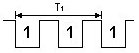
| Pendulum Period |
("Time", "GateState1")
"Time": Optional. A column of real numbers (the times of events)
"GateState1": A column of photogate states (1's and 0's)
Calculate the time between every other blocked event on Gate 1. If you
don't enter a "Time" column, the program will find one.
|
| Derivative Time Shift |
DerivativeTimeShift ("Y", "X"): returns the derivative
of "Y" with respect to "X". This function is specifically designed to
be used with photogate and picket fence data. The derivatives returned
are adjusted to estimate values at the start of the timing interval,
instead of the midpoint. For details see The Physics Teacher, Vol 35,
April 1997, p. 220. The article written by William Leonard is entitled
"The Dangers of Automated Data Analysis." Average velocity during the
time interval is equal to the instantaneous velocity at midpoint of the
time interval.
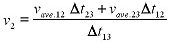
Where

|
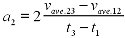
| Second Derivative Time Shift |
Numerical time-shifted second derivative("Y", "X")
"Y": A column of real numbers
"X": Optional. A column of real numbers
Numerical time-shifted second derivative. Calculates the second
numerical derivative of "Y" with respect to "X". The values are shifted
so that the derivatives are calculated at the midpoints between each
two values. If you don't supply an "X" column, the program will find
one.
|
| Count Events Over Time X |
("Time", "GateState", Interval)
"Time": A column of real numbers (the times of events)
"GateState": A column of photogate states (1's and 0's)
Interval: The time interval over which to count blocked events
Returns a column of the time intervals used in CountEventsOverTimeY.
|
| Count Events Over Time Y |
("Time", "GateState", Interval)
"Time": A column of real numbers (the times of events)
"GateState": A column of photogate states (1's and 0's)
Interval: The time interval over which to count blocked events
Counts the number of blocked events (1's) over each specified time
interval. Use this function to do "Radiation Counting" with a
photogate. Use with CountEventsOverTimeX to get a graphable pair of
columns.
|